
Buying
Can you mix different solar panels on one system?
Mixing solar panels on one system, why current decides in a series string and voltage in parallel, and what mismatched modules cost in lost output.
In short: You can mix modules, but the wiring decides what it costs. In one series string every module carries the same current, so the lowest current at maximum power sets the pace for all of them. In parallel, strings share one voltage, so the shorter string sets it. Across the catalogue, Imp runs from 9.94 A at the 10th percentile to 17.22 A at the 90th, so a replacement module bought on power alone can easily land on the wrong side of the one it joins.
The question usually comes up in one of two ways. A module on the roof breaks and the model is long out of production, or you want to add a few modules to an array that's already working. Either way the shop offers you whatever is current, and today's modules are bigger, carry more current and often work at a different voltage from the ones they sit next to.
Nothing about mixing is forbidden in itself. What it costs is set by two rules from basic circuit physics, and they point in opposite directions. PVEducation shows both on single cells, and the same rules hold for modules and strings of modules. Here are two cells in series that don't match, and what the pair delivers:
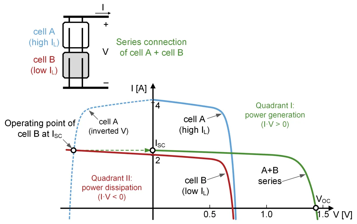

The pair's current is held to roughly the weaker cell's, and the stronger cell's extra current has nowhere to go. That picture is the whole of the series problem.
Series: the lowest current decides
Modules in a string are wired one after another, so the same current flows through each of them. Voltages add up; current doesn't. PVEducation puts it plainly for cells: the current from the combination can't exceed that of the poor cell.
For modules that means the string works at roughly the lowest Imp in it. A module that could deliver more current is held back to that figure and gives away the difference. Its voltage still counts in full, but power is voltage times current, so its share of the string's power falls in proportion to how far its Imp sits above the lowest one.
Voltage differences, on the other hand, are cheap in series. A module with a lower Vmp simply adds less to the string's total. As long as all the currents match, each module works at its own maximum power point and nothing is lost.
There's one more thing in series. Modules carry bypass diodes in the junction box. When a module can't carry the string current, its diode can conduct and route the current around it, so the inverter has a second choice: run the whole string at the low current, or skip the weak modules and run the rest at their own higher current. A tracker that scans the whole curve picks whichever gives more power. Neither is free, and PVEducation warns that when a mismatched pair is pulled down to low voltage, the good cells' extra current is dissipated in the poor cell, enough to damage the module for good. Taking that heat away from the weak cell is what the diode is there for.
Parallel: the lowest voltage decides
Two strings wired in parallel onto one inverter input share one voltage, and their currents add. PVEducation's page on parallel cells states it in two lines: the voltage across both is the same, the total current is the sum.
So the rule turns round. Different currents are fine in parallel: a string of high-current modules next to a string of low-current ones simply adds its larger share. Different voltages are what cost. The inverter's MPPT can only hold one voltage on that input, so if one string's working voltage is lower than the other's, the longer string is held below its best point.
The way to fix it is the module count. A string's voltage is the sum of its modules' Vmp, so a string of lower-voltage modules can match a string of higher-voltage ones by having more of them. SMA's documentation for running strings in parallel on one tracker sets exactly that condition: strings connected in parallel must have the same number of modules in series, be of the same technology and have the same MPP voltage, and SMA recommends connecting only modules of the same type to one tracker.
How far apart datasheets sit
How big a mismatch you can buy by accident depends on how far apart the datasheets are. Read the right-hand column as the range the middle eight in ten modules fall in:
| Datasheet figure | Median | Middle eight in ten |
|---|---|---|
| Vmp, working voltage | 37.9 V | 30.9 to 44.0 V |
| Imp, working current | 13.37 A | 9.94 to 17.22 A |
| Isc, short-circuit current | 14.13 A | 10.53 to 18.25 A |
Two more ratios tell you how the working point relates to the extremes. The median module's Vmp is 0.837 of its Voc, and its Imp is 0.945 of its Isc.
The table splits Isc, the current the inverter's limits are checked against, by rated power. Compare the class of the module on your roof with the class of the one you're about to buy:
| Rated power | Modules | Median Isc |
|---|---|---|
| Under 400 W | 1,997 | 10.2 A |
| 400 to 499 W | 5,013 | 14.0 A |
| 500 to 599 W | 3,423 | 14.1 A |
| 600 to 699 W | 2,726 | 16.1 A |
| 700 W and up | 765 | 18.4 A |
Check the module count next to each median before you lean on it. And treat the class median only as a first guess: two modules in the same class can still sit far apart, so the number that settles it is the Imp on the two datasheets.
A worked example
Take two made-up modules with round numbers, so you can follow the sums. Module A works at 40 V and 10 A, so it's rated at 400 W. Module B works at 32 V and 14 A, rated at 448 W: lower voltage, more current, more power, the direction the 10th percentile Vmp and 90th percentile Imp in the table point in.
Six A and four B in one series string. The ratings add up to 2,400 W plus 1,792 W, 4,192 W. The string's voltage is 240 V plus 128 V, 368 V. Its current is the lower Imp, 10 A. So it delivers 368 V times 10 A, 3,680 W: 512 W less than the ratings, a loss of 12.2 %. All of it falls on the B modules. Each one gives 320 W of its 448, so you paid for watts the string can't collect.
Ten A and ten B as two parallel strings. String A works at 400 V and 10 A, 4,000 W. String B works at 320 V and 14 A, 4,480 W. Together they're rated at 8,480 W. On one input they share the lower voltage, 320 V, and their currents add to 24 A, so they deliver 7,680 W: 800 W less, 9.4 %. This time the loss falls on string A, held 80 V below its best point.
Eight A and ten B in parallel. Now string A works at 320 V too. Both strings sit at their own best voltage, the currents add, and the pair delivers its full 7,680 W. Same two module types, no loss, because the count was chosen so the voltages agree.
That's the lesson in three lines: in series, match the current; in parallel, match the voltage, and you can get there by choosing how many modules go in each string.
The figure below runs the same arithmetic on your numbers. Each module is drawn as a box, width for its voltage and height for its current, so its area is its rated power. The dashed line is what the wiring allows; everything past it is lost.
What a mixed string loses
Set two module types, how many of each, and wire them in one series string or as two parallel strings, and see how much of their rated power the wiring can collect.
How this is computed
Each module is taken at its maximum power point, Vmp and Imp, and the sum of ratings is the number of modules of each type times Vmp times Imp. Series: the string voltage is the sum of every module's Vmp and the string current is the lowest Imp among the types present, so output = (nA × VmpA + nB × VmpB) × min(ImpA, ImpB). Parallel: each type is its own string, both held at the shorter string's voltage with each string at its own Imp, so output = min(nA × VmpA, nB × VmpB) × (ImpA + ImpB). The loss is the sum of ratings minus the output, and its share of the sum. A type with no modules drops out, and one type alone loses nothing.
Series is the bound with no bypass diode conducting. A real inverter can also let the bypass diodes skip the low-current modules and run the rest at their own higher current, and it takes whichever gives more power, so the real loss can be smaller than this one. Parallel treats each string's current as fixed at its Imp. Held below its Vmp a real string's current climbs a little towards its Isc, so the real loss there is somewhat smaller too, and strings far apart in voltage can push reverse current into each other, which is a question for fuses, not for this figure.
"Match string voltages" sets the number of B modules whose string voltage is closest to string A's. The model ignores temperature, shade, cable losses, ageing and the inverter's limits; whether a mixed string is safe is a question for the inverter datasheet, the module fuse ratings and your installer.
Illustrative model, not a measurement.
A second MPPT input, or optimisers
The cleanest way to add different modules is to keep them off the same tracker altogether. Many string inverters have two or more MPPT inputs, and each one finds its own working point. Put the old modules on one input and the new ones on the other, each as a string of identical modules, and neither rule applies across them. SMA's advice for running strings on a single tracker, same type and same MPP voltage, only bites when they share it.
Each input still has its own limits, though. A new string of high-current modules has to fit the current limits of the input it goes to, and its cold Voc has to stay under the inverter's maximum input voltage. Both checks are in Voc, Isc and your inverter. Some inverters have a smaller second input, as the example in that article does, so read the limits per input, not per inverter.
Where a second input isn't available, module-level electronics are the other route. A power optimiser on each module lets that module work at its own best point and converts its output to suit the string, and a microinverter turns each module into its own system. Both have their own input limits for voltage and current, so the new module has to fit the device it's paired with, and an optimiser maker can set rules on how far modules in one string may differ. Ask for those rules in writing before you buy.
Then there are the standards. IEC 62548-1, the international standard for PV array design, has clauses on series-parallel configuration and on backfeed and reverse currents, the current one string can push into another when they don't match and something goes wrong. Your installer works to it, or to the national rules built on it. Fuses and cables sized for the old strings may not be enough for a new one with a higher current.
What to do when you buy
Start with the datasheet of the module already on your roof, not the shop listing. You need its Vmp, Imp, Voc and Isc. If the label on the back of the module is still readable, it prints the same figures.
Then look for a replacement in this order:
- The same model, or one with a matching Imp and Vmp. For a single broken module in a series string this is the only clean answer. Within a few percent on Imp, the loss is small.
- For a series string, match the current first. A module with a lower Vmp but the same Imp costs you nothing; one with a higher Imp is wasted above the string's current, and one with a lower Imp drags every module in the string down to it.
- For a new string next to old ones, match the voltage. Choose the module count so the new string's total Vmp lands on the old string's, or put the new string on its own MPPT input.
- For larger changes, a separate input or module-level electronics. That keeps the old and the new from setting each other's working point.
Don't judge a mix by the rated power on the label. Two modules can both be sold as 450 W and still carry quite different currents, and that's the figure a series string runs on.
Who decides whether it's safe?
Your installer does. The figures here are about lost output; whether a mixed string is safe depends on the inverter's limits per input, the fuse rating of each module, the cable and the electrical rules in your country. A new module with a higher Isc can exceed a fuse or an input rating that the old ones respected, and nothing on the roof tells you until something trips or overheats.
What these figures can't tell you
Every catalogue figure here is a manufacturer's claim at standard test conditions. Modules in the field drift apart with age, dirt, shade and temperature, so even two identical modules are never perfectly matched; that background loss is there with or without a mix.
The worked example and the figure treat each module as a fixed voltage and current. A real module's current climbs a little when it's held below its Vmp, towards its Isc, so the parallel loss is smaller in practice than the straight-line sum suggests. In series, bypass diodes give the inverter a second option, skipping the weaker modules, and a tracker that finds it takes it when it gives more, so the true loss can be smaller than the figure's number. Neither changes which way the rules point.
Figures and denominators
How the figures above were computed. Every figure is recomputed from the catalogue and the live shop offers when the page is served, and each one counts only the modules or offers that publish the value.
The figures cover every listable module, 14,005 of them, as each manufacturer's datasheet states it. One datasheet usually covers a ladder of power ratings, so a datasheet with eight ratings is eight modules here. A module counts toward a figure when the values it needs sit in a plausible range: Vmp between 10 and 100 V, Imp between 1 and 25 A, Isc between 1 and 25 A, Voc between 10 and 100 V, Vmp between 0.7 and 0.95 of Voc and Imp between 0.85 and 0.995 of Isc. Values outside those ranges are data entry errors, not datasheet claims.
The power classes split modules by their rated power at standard test conditions: under 400 W, 400 to 499 W, 500 to 599 W, 600 to 699 W and 700 W and up. Each class figure is a median over the modules in that class that state both Voc and Isc.
The worked example uses two made-up modules with round numbers, 40 V and 10 A against 32 V and 14 A, so the arithmetic can be followed by hand. They are example inputs, not catalogue figures. The interactive figure starts module A at the catalogue median Vmp and Imp and module B at the 10th percentile Vmp and the 90th percentile Imp.
All 12 figures on this page and what each counts
| Figure | Value | Computed over |
|---|---|---|
| Maximum power point current at STC, 10th percentile | 9.94 A | 14,002 modules |
| Maximum power point current at STC, 90th percentile | 17.22 A | 14,002 modules |
| Maximum power point voltage at STC, median | 37.9 V | 13,925 modules |
| Maximum power point voltage at STC, 10th percentile | 30.9 V | 13,925 modules |
| Maximum power point voltage at STC, 90th percentile | 44.0 V | 13,925 modules |
| Maximum power point current at STC, median | 13.37 A | 14,002 modules |
| Short-circuit current at STC, median | 14.13 A | 14,002 modules |
| Short-circuit current at STC, 10th percentile | 10.53 A | 14,002 modules |
| Short-circuit current at STC, 90th percentile | 18.25 A | 14,002 modules |
| Vmp as a share of Voc, median | 0.837 | 14,000 modules |
| Imp as a share of Isc, median | 0.945 | 13,993 modules |
| Modules in the catalogue | 14,005 | 14,005 modules |
Related tools
Reference list
- PVEducation, Mismatch for Cells Connected in Series
- PVEducation, Mismatch for Cells Connected in Parallel
- PVEducation, Mismatch Effects in Arrays
- SMA Solar Technology, Polystring operation (inverter documentation)
- IEC 62548-1:2023, Photovoltaic (PV) arrays, Part 1, Design requirements (IEC webstore)
- IEC 62548-1:2023, preview with table of contents (VDE Verlag)